Instrument Design
The GUVI instrument consists of three major functional elements: a scanning imaging spectrograph (SIS) that obtains the spectral data, a detector processor which converts information recorded at the detector into wavelength and spatial information as required, and an interface to the TIMED spacecraft. The SIS subassembly consists of a cross track scanning mirror at the input to the telescope and spectrograph optics. The spectrograph is a Rowland circle mount which gives reasonable spatial imaging quality along the entrance slit axis. Lifetime studies and experience with the SSUSI detectors indicated that it was prudent to have two detectors at the focal plane of the instrument. The actual detector to be used is determined by the location of a mirror which can be inserted into the instrument's optical path. The detectors are custom built micro-channel plate intensified wedge-and-strip anode sealed tube units.
The imaging spectrograph builds multispectral images by scanning spatially across the satellite track. One dimension of the detector array contains 14 spatial pixels (along the spacecraft track), and the other dimension consists of 160 spectral bins over the range of 115 to 180 nm. In normal imaging mode, selected regions of the spectrum are down-linked as "colors". These "colors" preserve the physics of the observations while limiting the bandwidth required. The scan mirror sweeps the 14 spatial pixel footprint from horizon to horizon perpendicular to the spacecraft motion, producing one frame of 14 cross-track lines in 15 seconds. At an altitude of 625 km, looking at nadir, the footprint covers a width of 108 km at a height of 100 km above the ground. The viewing point 100 km above the ground moves by 104 km in one cycle of the scan mirror, so successive scans overlap at nadir. The detector processor bins the data into the selected colors.
The imaging mode scan cycle consists of a limb viewing section followed by an Earth viewing section. Limb viewing pixels are collected from 80.0° from nadir (the start of scan) to 67.2° from nadir. The limb viewing section has a cross track resolution of 0.4° per pixel, and consists of 32 cross track pixels by 14 along track pixels with five colors. At 80.0° from nadir and a spacecraft altitude of 625 km, the spectrograph will view a tangent point 519 km above the horizon, at a distance of 1215 km. At a more typical limb viewing angle of 68.8, the spectrograph will view a tangent point 152 km above the horizon, at a distance of 2530 km.
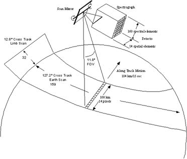
The variation in tangent point with view angle is shown in the "limb" portion. At a tangent point altitude of 152 km, the footprint of the instrument covers a distance of 530 km, but the viewing point only moves by 105 km in one 15 s scan mirror cycle. Therefore, the same pixel on the limb is re-sampled on five successive sweeps of the scan mirror on each orbit. The Earth viewing section has a cross track resolution of 0.8° per pixel, and contains 159 cross track pixels by 14 along track pixels and five colors. Pixels are collected from 67.2 from nadir to -60° from nadir (the end of scan).
In the spectrograph mode, the scan mirror is held at a fixed viewing angle (normally either the nadir direction for "ground truth" or on the limb for star calibrations) and the entire spectrum is down-linked. The along track dimension of the detector array is binned into 14 spatial pixels. Spectral data from 176 bins (the 160 bins which the "colors" are chosen from, plus 16 more on the long wavelength end) are produced for the 14 spatial pixels every 3.0 seconds.
There is, of course, a large range in the intensity of the scene that GUVI is expected to see. The detector electronics have a large dynamic range which can accommodate much of this range but some further flexibility was desired as well as the ability to incorporate a closed position. While we have some confidence in the first principles models used to predict the upper atmospheric radiance and the throughput of the system, we did not know the what the achieved quantum efficiency of the detectors would prove to be to within a factor of two. This was achieved by implementing two independent stepper motors which move metal vanes into position in front of the entrance to the spectrograph. These two vanes reduce the instrument's field of view from 0.78° to 0.30 or 0.18°. By activating both vanes at the same time a closed position is achieved. The intermediate width slit is intended for use during normal imaging mode operation. The widest slit would be used in imaging mode to increase the sensitivity should the optical efficiency of the system decrease over time or to minimize the statistical error for low count rate scenes such as when the FUV nightglow is to be observed. The narrowest slit improves the spectral resolution and reduces the instrument throughput. Any slit can be used in any mode of operation. Furthermore, the slit mechanism is designed so that two motors must fail (they are independent) in a specific (i.e. "closed") mode in order for the aperture to be "shuttered". The expected "failure" mode would be one that would leave us with a fixed slit.
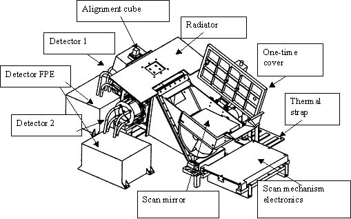
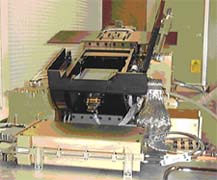
The major elements of the SIS are shown as is the implementation of two independent detectors. The TIMED spacecraft interface was specified to be IEEE 1553. A large scan mirror provides the horizon-to-horizon view for a telescope at the entrance to the spectrograph. There are two detectors, identical in form, fit, and function, which convert the incoming far ultraviolet photons into packets of charge which are located by the detector electronics. A once-open door protects the scan mirror from contamination during ground operations and launch.
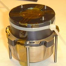
There are two redundant detectors, each with a focal plane electronics box to amplify and process signals. These signals are then sent to the Electronics Control Unit box inside the spacecraft bus. The SIS electronics box provides control signals for the scan mirror, slit selection, and pop-up mirror motors.GUVI detectors come from two different manufacturers: Photek and Siegmund Scientific. These photos illustrate the dimensions of the detector and the spectrograph to detector interface. The slots in the mounting flange are provided to account for uncertainty in the potted position of the tube and the rotation of the anode at the instrument's exit plane. The tube on the left was manufactured by Siegmund Scientific whereas the one on the right was manufactured by Photek. The Photek photo shows the tube during a test: this is not a flight configuration but does illustrate that the GUVI tubes were specified to be identical in form, fit and function so they are interchangeable.
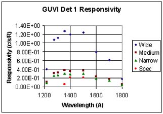
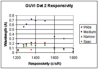
Five SSUSI units and the GUVI unit have been thoroughly characterized at the JHU/APL Optical Calibration Facility.6 The responsivity was measured at 16 along-slit angles and 20 wavelengths for both detectors, with the scan mirror set for nadir viewing.